Mobile Driving/Flying Cockpit with Motion and Tactile ( Build )

You should just be able to remove them with another (maybe bigger) magnet. :)

I have a magnet like that in a box with LOTS of foam around it and a BIG warning label marked DANGEROUS Magnet. It has drawn blood.

The problem is that while I'm absolutely sure it could get one of these magnets out. I'm not so sure I could ever get one of these little magnets separated again. They are tiny and there is no room to get purchase on them.

I have a bit of experience with neodymium magnets. They can be very painful to work with if you are not careful.
 
Last edited:
If I used pins than the magnets would not be needed. The parts can not be 3D printed with pins due to the print orientation of the parts. So I would have to insert metal pins. I could print the holes for metal pins, but I'm not excited about that.

If pins can´t be printed ( I have zero knowledge about that)
how about some printed ridges with corresponding grooves for fixation?

I´m a bit dubious about the lateral stability of the magnet alone when your reaching without looking.

MFG Carsten
 
I have a magnet like that in a box with LOTS of foam around it and a BIG warning label marked DANGEROUS Magnet. It has drawn blood.

The problem is that while I'm absolutely sure it could get one of these magnets out. I'm not so sure I could ever get one of these little magnets separated again. They are tiny and there is no room to get purchase on them.

I have a bit of experience with neodymium magnets. They can be very painful to work with if you are not careful.

Large neodymium is no joke.

Once upon a time in the early part of my career, I worked for a company designing Coriolis mass flow meters (I wrote all the DSP software and real-time OS code). These were basically high-precision speaker coil type drivers, and microphone sensors (two sides of the same coin). We had two versions...one for a 2" pipeline, and one for a 4" pipeline...both used neodymium magnets for the static fields. The 4" version used 6x 1" diameter X 1.25" tall magnets. Being precision machined parts for a 0.1% product, these did not have the nice "rounded" edges that you get with a commercial magnet, rather were "sharp". If set within 8" of each other on a table, they would attract each other, and slam together with enough force to SHATTER the two magnets.

At one point, the lead engineer was playing with the magnets, and accidentally let them sandwich the palm of his hand. They slipped to the outside edge of his hand and picked the skin by his pinky. He needed like 15 stiches.
 
If pins can´t be printed ( I have zero knowledge about that)
how about some printed ridges with corresponding grooves for fixation?

I´m a bit dubious about the lateral stability of the magnet alone when your reaching without looking.

MFG Carsten

The issue is that the front of the button boxes will be face down flat against the print bed. It would be possible to print an indentation like a chamfered slot or a hole, but raising it up would require supports which would make the button box face ugly.

You are making me rethink the Labels.

I was thinking that the labels would have to be magnet side down. I will be changing filament color for the lettering and assumed that would have to be on top. If I could find a way to get this with the lettering down and still get a good backing surface, I could potentially put a ridge in place to fit into a slot, possibly something like an X or plus sign with two axis for alignment.

I'll have to see how the magnets work before I pass judgement. if the magnets are in perfectly aligned holes they should allow the label to line up perfectly. What I don't know is how powerful these are at 0.6-0.9mm distance for this size. That will be the deciding factor.

There is another option. I could use a small dollup of never drying window glazing. I have many rolls of this stuff and it has excellent adhesion after repeatedly being pulled apart. Not everyone has something like this laying around. It is perfectly happy with flat surfaces.
 
You are making me rethink the Labels.

I´m so very sorry Sir :(

Another idea and then i will shut up: Promise !!

What about putting the magnets in the button box a little bit deeper ( ca 2mm)
and let the magnets in the label stand out about 1,5mm.

Should be easy to print ( I´m just guessing here) and you have the formfitting safety against sliding the
labels around.

my nurse is calling, I have to drink my beer and go to bed.

MFG Carsten

( never mind me, I just got whacked on SRS and am a little pissed :speechless:)
 
So I would have to insert metal pins. I could print the holes for metal pins, but I'm not excited about that.
One thing to consider is printing holes for metal pins slightly under-sized, and then heat-setting them into the print.

Just hold the pin over the slightly too small hole with pliers and apply light pressure while heating it with a soldering iron. Will give you a perfect fit every time that should withstand being withdrawn as many times as you need.

I use that trick to heat set threaded inserts into my prints, very handy for times you want to be able to screw parts together reliably.
 
That's something that I had forgotten about. I planned to get inserts to melt into place with a soldering iron, but have just been using square nuts.
 
In Prusa Slicer, I transitioned the layer height from .15mm to .07mm on the last layer to improve the label print quality and effectively iron the top layer out.

PrusaSlicerthinnerlayers.jpg


The deeper indentations that cast shadows are gone and the indentations in the letters are no longer visible to the naked eye.

By the time the printer reached the top chamfer of the red backing it is down to .1 mm so the edge has a smoother angle.

I need to purge the red filament more to keep the white letters from getting a pink hue to them, but I wasn't worrying about that for this print.

SmoothLetters.jpg
 
That's something that I had forgotten about. I planned to get inserts to melt into place with a soldering iron, but have just been using square nuts.
I recommend the heat set inserts. They're cheap, easy to work with, and have a knurled exterior that provides excellent grip once melted in; they're never coming back out short of total destruction of the plastic.

They also look nice and professional, feels good to work with parts that look and feel good. I have total confidence in firmly screwing into them, and taking them apart again later.
 
I've had inserts in a shoppong list on Amazon back from when I was still just thinking about buying a 3D printer. I just forgot to order them.
 
Last edited:
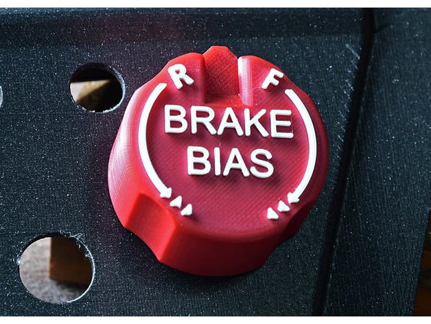
I printed out this brake bias wheel I found on Thingaverse and while I'll probably make one with white lettering that says Brake Bias in the center, the size is good and it feels pretty good in hand.

Here it is if you are interested.

However I found out is that this rotary switch is fragile. When I pressed the knob in place and tried it out the clicks felt positive and I was feeling pretty good about how this will work.

After I pulled the knob off something inside the rotary shifted such that the detents were almost gone.

BrakeKnob_5622.jpg


What I found was that if I pulled on the knob, I could feel the detents, but there was play in the rotary so it wouldn't stay that way.

The solution was to crimp the housing tight again. Now I can feel the detents again. This is just a warning about the fragile nature of these rotaries. I'm not sure how many cycles of crimping they will take before the prongs start to break off or the internals fail.

CrimpFit_5624.jpg


I also watched a Fusion 360 tutorial on creating knurling and found this knob also on Thingaverse that shows me that knurling will print well enough to use.

knurling_5626.jpg
 
Last edited:
I wonder if you could carefully solder the crimps around the body? Even just the center crimp on each side would probably be enough to resist a load.

I have the push-button type (B2 PN suffix), which upon inspection appears to be much more robust...presumably to handle the push-loads from the button action.

1607008490590.png


The two pins in the foreground are the NO button pins. These are coming out of the black resin lower plate, presumably where the button mechanism is located. No amount of vertical force that I could apply caused any flexion in the housing frame. The shaft feels like it has an internal stop at the terminus of the push-in movement---thus, keeping all forces within the brass mounting body and transferred to the mounting surface rather than through the shaft into the rotary mechanism and separating the body.

So, my guess is the CTS288V232R161B2 version doesn't have this concern.
 
Thanks for that! I I just orders some CTS288V232R161B2's

I think I like these. They are 45x23mm in size which seems right to me. I like the indentation so I have a reference point for position, but I'll need to see how it feels.

Assuming they work like I hope I'll post them to Thingaverse.

RottaryButtonMockup.jpg
 
Last edited:
I'm pretty happy with this first knob.

I did spend about 5 minutes cleaning up strings with an X-acto knife to get it to this point which still isn't perfect. but once again it looks much better to the naked eye.

BBknob_5630.jpg


I think these work well enough to share.
I'm printing the ABS knob with dark green and white next.

 
Last edited:
Stephan at CnC kitchen has a great episode on threaded inserts, top notch with consice quantification like all his work. I use the mid-range versions shown on the vid thumbnail and like them a lot. I have a bunch of the cheapo ones too and they're ok as well but the vid breaks it down nicely


That's a good one. That is the video that prompted me to put the following in my Amazon Shopping Cart.


Last edited:
I'm pretty happy with this first knob.


View attachment 424199


That looks awesome. :thumbsup:

MFG Carsten
 
I tweaked the diameter of the hole so it would go on just a bit easier and now I don't think it will ruin the rotaries, but I still have 5 of the B2 variation ordered. I think TC and ABS typically have an On/Of as well as adjustability.

However the hole is currently at a depth that gives this about .5mm clearance from the top of the button box. I'll need more clearance for the B2 variety so they can press down.

Edit: The B2 looks like it may have a very slightly longer shaft and the click is only 0.5mm. These currently have about .5mm clearance when fully pressed on, so I may not need to modify anything.

Ordered some Pearl Blue and plain black filament.

ABS_5638.jpg
 
Last edited:
The right side was going to look "wrong" if it wasn't skinned in a similar way. So I created a 2 part USB Mount that attaches to the right side of the vertical mount and makes it look more unified.

That said, this is a half step since it seems obvious that I will need to integrate the SC2 Cover with both sides to make it a continuous dash :)

FullDash.jpg
FullDashTop.jpg


These prints will take a while. The one below will finish this afternoon ( Now Saturday )

Edit: Version 2 iterations below. I had the cable slot facing down on V1 and it left a chunk unsupported. Whoops! I'm trying to design things so they don't require supports. But I was able to put the failed print in place and verify a few things. There was one clearance issue. I also moved the USB mount a bit further back and a bit further to the right.

USBBackV2.jpg


The print below will finish sometime Sunday afternoon. I made a number of modifications to this as well. Closing the hole. This is still a 20 hour print.

USBFrontV2.jpg


This also allows more test fitting even if it is on the right side, this is "mostly" symetrical from the left side.
 
Last edited:
Ordered these soldering tips for my Weller soldering iron to go with the threaded inserts that I ordered.


Question: @mechsicko @Aurich

How large a hole do you make for these inserts and what soldering iron temperature do you typically use?

I was assuming I would make the hole the same diameter as the smallest OD diameter.

That CNC video showed 200C or about 400F.

My intention at the moment is to use these for the following:

1. M3 mounts for the 64 input button board
2. M5 headset hangar
3. M5 Phone mount.

I still think the square nuts are good for many of the other points.
 

Latest News

What brands would you like to see with more engagement in simracing?

  • Ferrari

    Votes: 322 35.0%
  • Porsche

    Votes: 356 38.7%
  • BMW

    Votes: 338 36.8%
  • McLaren

    Votes: 220 23.9%
  • Toyota

    Votes: 337 36.7%
  • Intel

    Votes: 116 12.6%
  • AMD

    Votes: 170 18.5%
  • Gigabyte

    Votes: 81 8.8%
  • IBM

    Votes: 49 5.3%
  • Elgato

    Votes: 66 7.2%
  • Microsoft

    Votes: 134 14.6%
Back
Top